


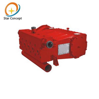
600S Triplex Plunger Pump
The 600S triplex plunger pump is a high-pressure positive displacement reciprocating pump that uses three staggered plungers to achieve fluid intake and pressurized discharge. It is widely used in oilfield cement fracturing, acidizing operations, and chemical liquid transportation, where high flow rates and stable pressure are required.
Product advantages
High-efficiency output: Equipped with a 600 hp drive, it provides a high flow rate of 12,000 L/min.
Multiple plunger sizes: Available in 3″, 3.5″, 4″, and 4.5″ plunger sizes to meet different flow and pressure requirements.
Stable flow: The three-cylinder design controls flow pulsation within ±5%, ensuring smoother system operation.


Product Specification
|
Pump Model |
600S triplex plunger pump |
|
Maximum Input Power |
447kW(600hp) |
|
Maximum Connecting Rod Load |
445000N(100000 lbs) |
|
Stroke |
152.4mm(6") |
|
Maximum stroke |
450rpm |
|
Gear Ratio of Reduction Gear |
4.61:1 |
|
Dimension |
1292×1366×607mm |
|
Length X Width X Height |
(50.87"×53.78"×32.28") |
|
Weight |
2155kg(4751 lb) |
|
Piston Diameter Inches mm |
Pump strokes(rpm) |
|||||||||
|
50 |
120 |
200 |
300 |
450 |
||||||
|
Displa ement GPM (L/min) |
Pressure Psi (MPa) |
Displacement GPM (L/min) |
Pressure Psi (MPa) |
Displacement GPM (L/min) |
Pressure Psi (MPa) |
Displacement GPM (L/min) |
Pressure Psi (MPa) |
Diaplacement GPM (L/min) |
Pressure Psi (MPa) |
|
|
3" (76.2) |
28 (104) |
14141 (97.5) |
66 (250) |
14098 (97.2) |
110 (417) |
8456 (58.3) |
165 (625) |
5642 (38.9) |
248 (938) |
3756 (25.9) |
|
3.5" (88.9) |
37 (142) |
10399 (71.7) |
90 (341) |
10341 (71.3) |
150 (568) |
6208 (42.8) |
225 (851) |
4148 (28.6) |
337 (1277) |
2756 (19) |
|
4" (101.6) |
49 (185) |
7962 (54.9) |
118 (445) |
7919 (54.6) |
196 (741) |
4757 (32.8) |
294 (1112) |
3176 (21.9) |
441 (1668) |
2118 (14.6) |
|
4.5" (114.3) |
62 (235) |
6295 (43.4) |
149 (563) |
6266 (43.2) |
248 (938) |
3756 (25.9) |
372 (1407) |
2509 (17.3) |
558 (2111) |
1668 (11.5) |
Note: Parameters are based on 100% volumetric efficiency and 90% mechanical efficiency.
The table shows stroke frequency, hydraulic end displacement at different gear positions, and pressure at full water power (100%) for each displacement. This data is for selection by wellsite engineers and operators. The pump operates intermittently under maximum pressure. Continuous operation at maximum pressure should not exceed 1 hour, and at 80% of maximum pressure, it should not exceed 3 hours to extend service life.
Main Components
1. Power End Assembly of 600S Triplex Plunger Pump;
2. Gearbox Assembly 600S Triplex Plunger Pump
3. Hydraulic End Assembly of 600S Triplex Plunger Pump
4. Suction Pipe Assembly of 600S Triplex Plunger Pump
4.1 600S Triplex Plunger Pump Power End Assembly
The power end consists of the crankshaft, connecting rods, crosshead, small connecting rods, bearings, crankshaft housing, crosshead housing, and stuffing box.
4.1.1 Power End Housing
(1) The housing employs a steel welded structure and undergoes stress-relief treatment.
(2) Crosshead slide sleeves are bolted for easy disassembly.
(3) Crankcase undergoes precision boring.
4.1.2 Crankshaft
(1) Monolithic design, alloy steel forging.
(2) Heat treated and polished.
(3) Supported by four heavy-duty cylindrical roller bearings.
4.1.3 Crosshead
Ductile iron construction with full cylindrical design and oil grooves.
4.1.4 Connecting Rod
Precision machined from high-strength cast steel.
4.1.5. Crosshead Guide Bushings
Designed as replaceable semi-cylindrical shapes, precision-machined from alloy cast iron.
4.1.6. Connecting Rod Pins
(1) Made of alloy steel with surface hardening treatment.
(2) Secured in crosshead with standard bore retaining rings after installation.
(3) Precision-machined after heat treatment.
4.1.7. Power End Assemblyof 600S Triplex Plunger Pump Schematic Diagram


4.2 Gearbox Assembly
The gearbox assembly primarily consists of: gearbox housing, large gear, small gear, bearings, pressure plate, etc.
4.2.1 Housing
(1) Precision-bored after stress-relief heat treatment of welded high-strength steel.
(2) Parallel-shaft design.
4.2.2. Large Gear
(1) Precision-machined from high-strength alloy steel.
(2) Case-hardened and quenched tooth surfaces.
(3) Supported by two heavy-duty tapered roller bearings.
4.2.3. Pinion Shaft
(1) Integral machining after heat treatment of alloy steel.
(2) Gear surfaces carburized and quenched.
(3) Supported by two heavy-duty tapered roller bearings.
4.2.4 Gearbox Assembly Schematic

A. Gearbox mounted on the left of 600S Triplex Plunger Pump

B. Gearbox mounted on the right side of 600S Triplex Plunger Pump
The random spare parts list (by plunger) is as follows. Part numbers may vary depending on plunger diameter, but the quantities remain the same.

4.4 Hydraulic End Assembly of 600S Triplex Plunger Pump
The hydraulic end consists of the pump head body, valve body assembly, piston, packing, valve cover, and other components. As shown in the figure.
4.4.1 Pump Head Body
(1) The pump head body is an alloy steel forging with an integral structure.
(2) It undergoes heat treatment and non-destructive testing.
4.4.2 Plunger
(1) Made of low-carbon steel with a wear-resistant alloy powder coating for enhanced abrasion and corrosion resistance.
(2) Connected to the small connecting rod via a clamp for easy disassembly.
4.4.3 Valve Assembly of 600S Triplex Plunger Pump
(1) Suction and discharge valve assemblies are identical.
(2) Features an aerofoil-guided conical valve.
(3) Valve seal ring is made of polyurethane rubber.
(4) Valve spring is cylindrical.
4.4.4. Plunger Packing
(1) Precision-pressed packing seal assembly.
(2) Precision-machined bronze joint ring.
(3) Packing with varying compositions suits common media including hydrochloric acid, cement, fracturing slurry, hydrocarbons, toluene, etc. Operates across a wide range of ambient and fluid temperatures.
Spare Parts List
The random spare parts list (by plunger) is as follows. Part numbers may vary depending on plunger diameter, but the quantities remain the same.
|
Item |
Name |
Qty |
Component |
|
1 |
Sealing ring |
3 |
Exhaust cover assembly |
|
2 |
Oil seal |
3 |
Sealing Assembly |
|
3 |
Spacer ring |
3 |
Sealing Assembly |
|
4 |
Pressure Main Ring |
3 |
Sealing Assembly |
|
5 |
Self-lubricating first ring |
3 |
Sealing Assembly |
|
6 |
O Ring |
3 |
Sealing Assembly |
|
7 |
O Ring |
3 |
Sealing Assembly |
|
8 |
Retaining ring |
3 |
Sealing Assembly |
|
9 |
Retaining ring |
3 |
Sealing Assembly |
|
10 |
Verne rubber |
6 |
Valve Assembly |
|
11 |
Vertex O-ring |
6 |
Valve Assembly |
|
12 |
Sealing ring |
3 |
Inhalation Cover Assembly |
|
13 |
O-ring 140*5.3 |
3 |
Suction manifold |


FAQ
Q: What is the price of the 600S Triplex Plunger Pump?
A: The price varies depending on order quantity and customization requirements. Please contact us for a detailed quote.
Q: How can I enjoy discounts on this product?
A: We offer bulk purchase discounts and provide further discounts based on long-term cooperation.
Q: Does the product offer customization services?
A: Yes, we offer customization based on your needs, including plunger size, pump body material, and more.
Q: What is the lead time for customized production?
A: The typical production lead time for customization is 4-6 weeks, depending on the specifics of the customization.
Q: What is the warranty period for the pump?
A: We provide a 1-year warranty for the 600S Triplex Plunger Pump. If any non-human faults occur within the warranty period, we will repair or replace the parts free of charge.
Hot Tags: 600s triplex plunger pump, China 600s triplex plunger pump manufacturers, suppliers, factory, small triplex pumps, triplex pressure washer pump, triple plunger pump, aaa industrial triplex, aaa triplex plunger pump, pressure washer plunger pump
You Might Also Like



Send Inquiry